Download: project files
This DE2 project uses a look-up table to generate output to one of the audio channels. The crucial modification of the main module (audio2) is shown below:
// instantiate the look-up table
reg [7:0] index;
parameter PERIOD = 48;
sine_table sig1(
    .index(idx),
    .signal(audio_outR)
);

// clock out the signal values
always @(negedge AUD_DACLRCK)
    if (index<PERIOD-1) index <= index + 1'b1;
    else index <= 8'h00;

// not using the other audio output, so zero it out
assign audio_outL = 16'h0000;
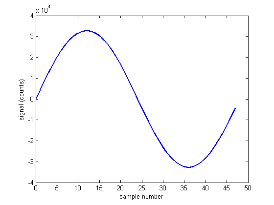
This is the signal being generated:
The measured frequency is 976.56 Hz
The design clock frequency of Audio CODEC is 18.432 MHz.
This yields 18.432 MHz / (48 KHz samples * 16 bit/channel * channels/sample) = 12
The Audio PLL generates 2/3 of its input clock freqeuency (27 MHz) or 18 MHz. Working backwards gives a clock divisor of 18 MHz / (48 KHz * 16 * 2) = 11.7185, which is not an integer number.
The actual sample frequency is 18 MHz / (16 * 2 * 12) = 46.875 kHz.
Our wave table has 48 points per cycle, for a calculated frequency of 976.5625 Hz, in good agreement with the measured frequency (on the Agilent multimeter) of 976.56 Hz.
Note that the sine wave is slightly clipped at a volume setting of 0x7B (maximum value is 0x7F).
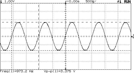
HP volume set to 0x7B
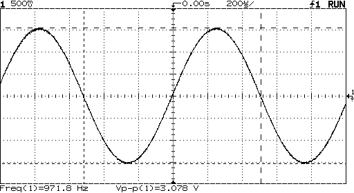
HP volume set to 0x7A
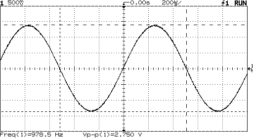
HP volume set to 0x79
Maintained by John Loomis, last updated Sun Mar 09 14:19:56 2008