Figure 1. Pin Diagram of LM348 IC
This lab explores some circuits using the LM348 operational amplifier
Do the following exercises. Report your results by creating a Word document and submitting it in Isidore. Submit one report per group.
This laboratory explores some circuits using the LM348 operational amplifier, which you should find in the blue toolboxes and in your parts kit. You will use the triple-output DC supply on the lab bench to provide the ±12-volt power to the op-amp. Figure 6 at the end of this document shows recommended power connections. Connect the +12-volt supply to Va and the −12-volt supply to Vb. Connect the COM output to ground. The pin diagram for the LM348 is reproduced in Figure 1.
Figure 1. Pin Diagram of LM348 IC
| Frequency | 400 Hz | 700 Hz | 1 kHz | 5 kHz | 10 kHz | 50 kHz |
|---|
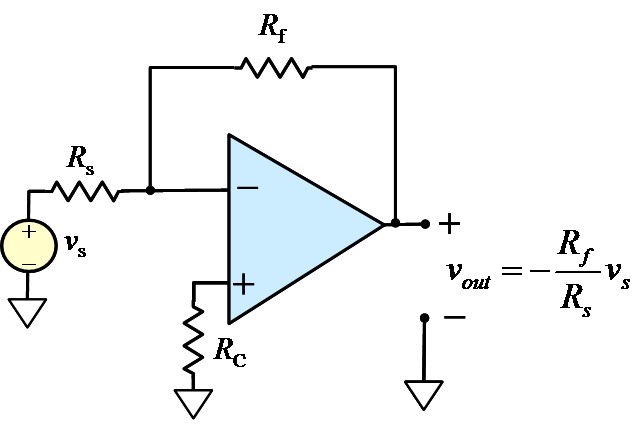
Figure 2. Inverting amplifier
| Frequency | 400 Hz | 700 Hz | 1 kHz | 5 kHz | 10 kHz | 50 kHz |
|---|
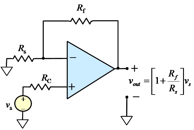
Figure 3. Noninverting amplifier
| Frequency | 400 Hz | 700 Hz | 1 kHz | 5 kHz | 10 kHz | 50 kHz |
|---|
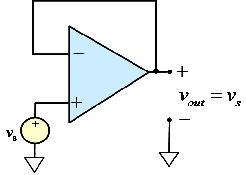
Figure 4. Voltage follower.
| Frequency | 400 Hz | 700 Hz | 1 kHz | 5 kHz | 10 kHz | 50 kHz |
|---|
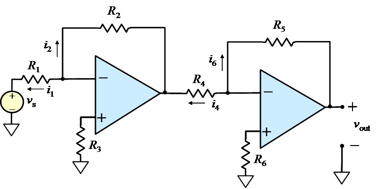
Figure 5. Cascaded amplifier
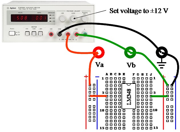
Figure 6. Connecting prototype board to the triple-output power supply.
Maintained by John Loomis, last updated 9 July 2014