Ion implanters are classified according to energy and/or current rates. The higher the energy, the deeper the ions penetrate
High energy is needed for well implants. Implanters contain the following systems.
Vacuum is crucial to implantation because it removes most of the densely packed molecules that block ion flow. A variety of roughing and cryopumps are used to produce the vacuum that remains throughout the process.
Wafers are mounted on a disk that will spin about 800 rpm.
The disk assembly can be tilted as needed to prevent channeling where ions can tunnel through the Silicon crystal matrix.
Sideways scanning of the spinning disk insures . more uniform implanting of the entire wafer
Some components of the implanter include high voltage soruce, a gas cabinent, and the source assembly.
| Dopant | Gas |
|---|---|
| Boron | BF3 |
| Phosphorous | PH3 |
| Arsenic | AsH3 |
Most of these gases are highly toxic and must be stored in a well-venilated gas assembly system.
Voltages up to 90 kV are required to ionize the dopant gases.
Inside the source assembly is a tungston filament which when powered heats to a very high temperature releasing electrons which are propels to the positive-charged chamber walls. A magnet forces the electrons into a spiraling path, which increases the number of collisions between the electrons and gas molecules.
The ionized particles move into the arc chamber, attracted by the negative potential of the extraction assembly. Excess electrons are channeled into a thin protective sheet which help prevent the ion beam from spreading. The beam then encounters a large curved electromagnet which serves to select the desired ion components, based on mass and charge. A water cooling assembly dissipates the heat from heavier or lighter ions that strike the walls of the magnet. For ions to penetrate to the required depth they must have a certain kinetic energy KE = nV. This occurs in the acceleration column. Beam energies of up to 9 million electron volts are typical. Quadrapole magnets are used to focus the beam. An AC electric field is used to first attract positive ions and then repell them as they pass through the focussing assemblies. Once beams have been established, the flat faraday plates blocking the beam are moved out of the way and implantation begins.
The ions cause substantial atomic-level damage to the crystal, knocking a thousand atoms around before stopping inside the lattice. After implantation stops, the wafers undergo an annealing process to repair the substrate damage. At about 1000 C, thermal diffusion and annealing can occur. Thermal diffusion continues for a significant period of time to allow the ions to diffuse uniformly into the substrate.
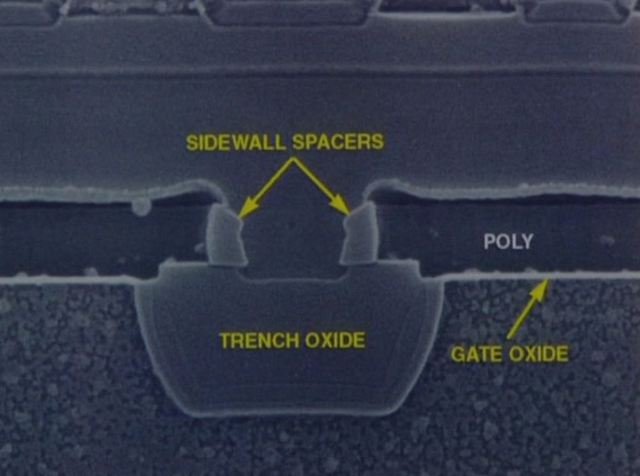
More advanced processes create substrate trenches to adjust the threshold voltages.
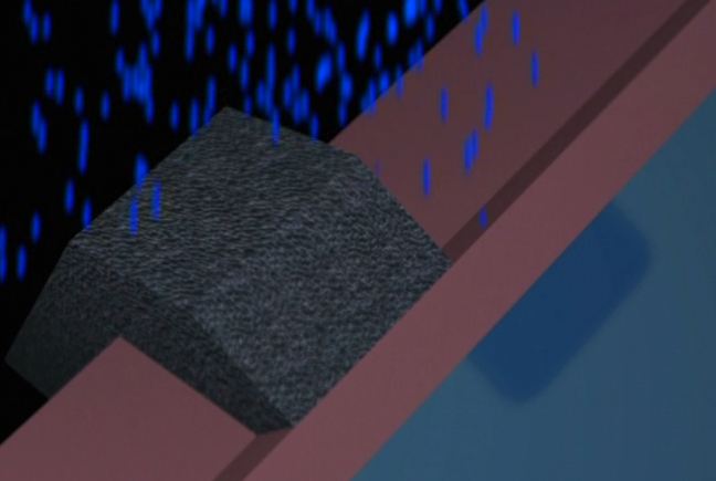
Scanning electrodes are used (at about 900 Hz) to move the Boron beam from side to side across the wafer.
As channels become shorter, there are edge effects near the border. This is improved through the use of halo implants at the edges of the channel. The wafer must be tilted at about at 45 degree angle to allow the ions to impact at the right orientation. Higher atomic-weight materials such as Ge and Sn are used. As solid sources they are placed in electrode pans for ionization
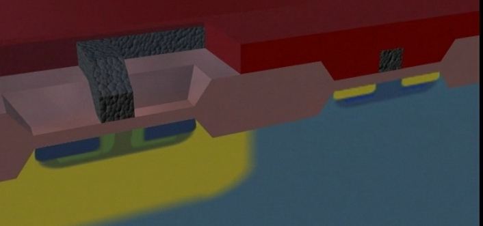
The lightly doped active regions are implanted in a low energy/high current implanter. This system also uses mechanical scanning. Because this is a shallow implant the ion beam does not need to be accelerated.
To activate the drain regions, the wafers undergo further annealing in separate annealing chambers. Rapid annealing can be done with light using Tungston lamps or heat using rapid heating furnaces, such a bell-jar system. Wafers may be heated only 1 – 2 minutes at about 1000 C.
Maintained by John Loomis, last updated 8 April 2015