Download: testbed1.zip.
The project testbed1 is a graphics environment for
developing procedures for drawing electronic symbols.
The onPaint of the class CChildView is
used to position various symbols, drawn with routines from symbols.cpp.
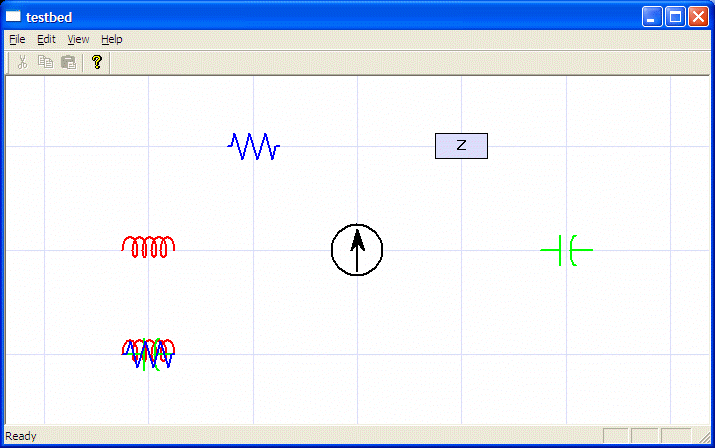
The basic circuit components were designed to be centered in a rectangle 5 units wide and 2.5 units high. The current source is enclosed in a circle 5 units in diameter. The midpoint of each symbol is the origin.
Symbols are then scaled by a factor of ten and translated to their final position. Adding a rotational degree of freedom should be easy.
I think a rotational variable such that 1 is -90 degrees, 2 is 180 degrees, and 3 is +90 degrees makes sense. I expect a -90 degree rotation to be the most common. A rotation of 0.5 would be -45 degrees, 1.5 is -135 degrees, and so forth. Question: should 2.5 be +135 degrees and 3.5 45 degrees or should 2.5 be 45 degrees and 3.5 be 135 degees? I am inclined toward the latter, using numbers above 2 to measure counterclockwize from the positive x-axis.
ChildView.cppvoid CChildView::OnPaint()
{
CPaintDC dc(this); // device context for painting
// Handle isotropic mapping
CRect win;
GetClientRect(&win);
dc.SetMapMode(MM_ISOTROPIC);
dc.SetWindowExt(480,-320);
dc.SetViewportExt(win.Width(),win.Height());
dc.SetViewportOrg(win.Width()/2,win.Height()/2);
// Draw a reference grid
CPen pen (PS_SOLID,0,RGB(220,220,255));
CPen *oldpen = (CPen *) dc.SelectObject(&pen);
int u = 4*point2::resolution;
for (int i=-4; i<=4; i++) {
int v = i*point2::resolution;
dc.MoveTo(-u,v);
dc.LineTo(u,v);
dc.MoveTo(v,-u);
dc.LineTo(v,u);
}
dc.SelectObject(oldpen);
int w = 5;
dc.Ellipse(-w,-w,w,w);
void drawResistor(CDC &dc, Vec2 &loc);
void drawImpedance(CDC &dc, Vec2 &loc);
void drawCapacitor(CDC &dc, Vec2 &loc);
void drawInductor(CDC &dc, Vec2 &loc);
void drawCurrentSource(CDC &dc, Vec2 &loc);
drawResistor(dc,Vec2(-1,1));
drawInductor(dc,Vec2(-2,-1));
drawCapacitor(dc,Vec2(-2,-1));
drawImpedance(dc,Vec2(1,1));
drawResistor(dc,Vec2(-2,-1));
drawInductor(dc,Vec2(-2,0));
drawCapacitor(dc,Vec2(2,0));
drawCurrentSource(dc,Vec2(0,0));
}
symbols.cpp//
#include "stdafx.h"
#include "point2.h"
void drawResistor(CDC &dc, Vec2 &loc)
{
const double w = 2.5/7.0;
const double y = 1.25;
Vec2 pts[] = { Vec2(-7*w,0), Vec2(-6*w,0), Vec2(-5*w,y), Vec2(-3*w,-y), Vec2(-w,y), Vec2(w,-y),
Vec2(3*w,y), Vec2(5*w,-y), Vec2(6*w,0), Vec2(7*w,0) };
int npts = sizeof(pts)/sizeof(pts[0]);
int i;
CPoint *cpts = new CPoint[npts];
for (i=0; i<npts; i++) {
pts[i].scale(0.1).translate(loc);
point2::convert(pts[i],cpts[i]);
}
/*
CRect rect(0,0,2,2);
dc.DPtoLP(&rect);
int width = rect.Width();
CString str;
if (width<2) width = 2;
str.Format("pen width %d",rect.Width());
dc.TextOut(50,-50,str);
*/
int color = RGB(0,0,255);
CPen pen(PS_SOLID,2,color);
CPen *oldpen = (CPen *) dc.SelectObject(&pen);
dc.Polyline(cpts,npts);
dc.SelectObject(oldpen);
delete [] cpts;
}
void drawImpedance(CDC &dc, Vec2 &loc)
{
Vec2 pts[] = { Vec2(-2.5,1.25), Vec2(2.5,-1.25) };
int i, npts;
npts = sizeof(pts)/sizeof(pts[0]);
CPoint *cpts = new CPoint[npts];
for (i=0; i<npts; i++) {
pts[i].scale(0.1).translate(loc);
point2::convert(pts[i],cpts[i]);
}
CBrush brush(RGB(220,220,255));
CBrush *oldbrush = (CBrush *) dc.SelectObject(&brush);
CRect rect(cpts[0],cpts[1]);
dc.Rectangle(rect);
dc.SelectObject(oldbrush);
int mode = dc.GetBkMode();
dc.SetBkMode(TRANSPARENT);
CString str("Z");
dc.DrawText(str,rect,DT_CENTER | DT_SINGLELINE | DT_VCENTER);
dc.SetBkMode(mode);
delete [] cpts;
}
void drawCapacitor(CDC &dc, Vec2 &loc)
{
Vec2 pts[] = { Vec2(-2.5,0), Vec2(-0.5,0), Vec2(0.5,0), Vec2(2.5,0), Vec2(-0.5,-1.5), Vec2(-0.5,1.5),
Vec2(1,-1.5), Vec2(0.5,-1.5), Vec2(0.5,-0.5), Vec2(0.5,0.0), Vec2(0.5,0.5),
Vec2(0.5,1.5), Vec2(1.0,1.5) };
int npts = sizeof(pts)/sizeof(pts[0]);
int i;
CPoint *cpts = new CPoint[npts];
for (i=0; i<npts; i++) {
pts[i].scale(0.1).translate(loc);
point2::convert(pts[i],cpts[i]);
}
int color = RGB(0,255,0);
CPen pen(PS_SOLID,2,color);
CPen *oldpen = (CPen *) dc.SelectObject(&pen);
for (i=0; i<6; i+=2) {
dc.MoveTo(cpts[i]); dc.LineTo(cpts[i+1]);
}
dc.PolyBezier(cpts+6,7);
dc.SelectObject(oldpen);
delete [] cpts;
}
void drawInductor(CDC &dc, Vec2 &loc)
{
Vec2 spts[] = { Vec2(-2.75,0), Vec2(-2.75,2), Vec2(-1.25,2), Vec2(-1.25,0),
Vec2(-1.25,-1), Vec2(-1.75,-1) };
int i, j, k, npts;
npts = sizeof(spts)/sizeof(spts[0]);
Vec2 *pts = new Vec2[5*npts];
k = 0;
for (j=0; j<5; j++) {
Vec2 t(j,0.0);
for (i=0; i<npts; i++) {
pts[k++]=spts[i]+t;
}
}
npts = 4*npts+4;
double w = pts[npts-1][0];
w = 0.25/w;
CPoint *cpts = new CPoint[npts];
for (i=0; i<npts; i++) {
pts[i].scale(w).translate(loc);
point2::convert(pts[i],cpts[i]);
}
int color = RGB(255,0,0);
CPen pen(PS_SOLID,2,color);
CPen *oldpen = (CPen *) dc.SelectObject(&pen);
dc.PolyBezier(cpts,npts);
dc.SelectObject(oldpen);
delete [] pts;
delete [] cpts;
}
void drawCurrentSource(CDC &dc, Vec2 &loc)
{
Vec2 pts[] = { Vec2(-2.5,-2.5), Vec2(2.5,2.5), Vec2(0,-2), Vec2(0,2), Vec2(-0.7,0),
Vec2(0,0.8), Vec2(0.7,0)};
int i, npts;
npts = sizeof(pts)/sizeof(pts[0]);
CPoint *cpts = new CPoint[npts];
for (i=0; i<npts; i++) {
pts[i].scale(0.1).translate(loc);
point2::convert(pts[i],cpts[i]);
}
CPen pen(PS_SOLID,2,RGB(0,0,0));
CPen *oldpen = (CPen *) dc.SelectObject(&pen);
CRect rect(cpts[0],cpts[1]);
dc.Ellipse(&rect);
dc.MoveTo(cpts[2]); dc.LineTo(cpts[3]);
CBrush brush(RGB(0,0,0));
CBrush *oldbrush = (CBrush *) dc.SelectObject(&brush);
dc.Polygon(cpts+3,npts-3);
dc.SelectObject(oldbrush);
dc.SelectObject(oldpen);
delete [] cpts;
}
The superimposed symbols on the lower-left checks that the symbols all start and stop at the same place and are approximately the same height.
Maintained by John Loomis, updated Thu Feb 01 21:52:42 2007