function xp = project_points_small(X,om,T,f,c,k,alpha)
f = fc;
c = cc;
k = kc;
alpha = alpha_c;

%project_points2.m
%
% xp = project_points2(X,om,T,f,c,k,alpha)
%
%Projects a 3D structure onto the image plane.
%
%INPUT: X: 3D structure in the world coordinate frame (3xN matrix for N points)
%       (om,T): Rigid motion parameters between world coordinate frame and camera reference frame
%               om: rotation vector (3x1 vector); T: translation vector (3x1 vector)
%       f: camera focal length in units of horizontal and vertical pixel units (2x1 vector)
%       c: principal point location in pixel units (2x1 vector)
%       k: Distortion coefficients (radial and tangential) (4x1 vector)
%       alpha: Skew coefficient between x and y pixel (alpha = 0 <=> square pixels)
%
%OUTPUT: xp: Projected pixel coordinates (2xN matrix for N points)
%
%Definitions:
%Let P be a point in 3D of coordinates X in the world reference frame (stored in the matrix X)
%The coordinate vector of P in the camera reference frame is: Xc = R*X + T
%where R is the rotation matrix corresponding to the rotation vector om: R = rodrigues(om);
%call x, y and z the 3 coordinates of Xc: x = Xc(1); y = Xc(2); z = Xc(3);
%The pinehole projection coordinates of P is [a;b] where a=x/z and b=y/z.
%call r^2 = a^2 + b^2.
%The distorted point coordinates are: xd = [xx;yy] where:
%
%xx = a * (1 + kc(1)*r^2 + kc(2)*r^4 + kc(5)*r^6)      +      2*kc(3)*a*b + kc(4)*(r^2 + 2*a^2);
%yy = b * (1 + kc(1)*r^2 + kc(2)*r^4 + kc(5)*r^6)      +      kc(3)*(r^2 + 2*b^2) + 2*kc(4)*a*b;
%
%The left terms correspond to radial distortion (6th degree), the right terms correspond to tangential distortion
%
%Finally, convertion into pixel coordinates: The final pixel coordinates vector xp=[xxp;yyp] where:
%
%xxp = f(1)*(xx + alpha*yy) + c(1)
%yyp = f(2)*yy + c(2)
%
%
%NOTE: About 90 percent of the code takes care fo computing the Jacobian matrices
%
%
%Important function called within that program:
%
%rodrigues.m: Computes the rotation matrix corresponding to a rotation vector
%
%rigid_motion.m: Computes the rigid motion transformation of a given structure
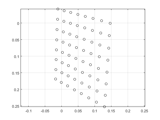
[~,n] = size(X);

Y = rigid_motion(X,om,T);

inv_Z = 1./Y(3,:);

x = (Y(1:2,:) .* (ones(2,1) * inv_Z)) ;

plot(x(1,:),x(2,:),'ko');
grid
axis equal
axis ij
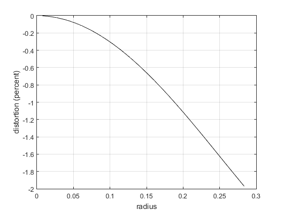
% Add distortion:

r2 = x(1,:).^2 + x(2,:).^2;
r4 = r2.^2;
r6 = r2.^3;

% Radial distortion:

cdist = 1 + k(1) * r2 + k(2) * r4 + k(5) * r6;

[r ndx] =sort(sqrt(r2));

figure
plot(r,(cdist(ndx)-1)*100,'k');
grid
xlabel('radius');
ylabel('distortion (percent)');

xd1 = x .* (ones(2,1)*cdist);
% tangential distortion:

a1 = 2.*x(1,:).*x(2,:);
a2 = r2 + 2*x(1,:).^2;
a3 = r2 + 2*x(2,:).^2;

delta_x = [k(3)*a1 + k(4)*a2 ;
    k(3) * a3 + k(4)*a1];

xd2 = xd1 + delta_x;
Add Skew:
xd3 = [xd2(1,:) + alpha*xd2(2,:) ; xd2(2,:)];
Pixel coordinates:
if length(f)>1,
    xp = xd3 .* (f(:) * ones(1,n))  +  c(:)*ones(1,n);
else
    xp = f * xd3 + c*ones(1,n);
end;
maximum error
fprintf('maximum diff from Bouguet: %g %g\n',max(abs(xp-y_kk)'));
maximum diff from Bouguet: 0 0