EGR203 Electric/Electronic Circuits Assignment 2(b)
- Determine the Thévenin voltage and resistance of the circuit
below. Use the Thévenin
equivalent circuit to determine the voltage across and
current flowing through the load resistor.
| R1 (ohms) | R2
(ohms) | R3 (ohms)
| RL (ohms) | Vs (volts)
|
| 200 | 800 | 140 | 600 | 12
|
- Find the load resistance for maximum power transfer in the
circuit above.
- Replace the load resistance in the circuit above with a 9 Volt
battery. Find the current flowing through the battery. Is the battery
being charged (power absorbed) or discharged (power generated)?
- Find the Thévenin voltage and resistance for the circuit below.
Assume R = 90.
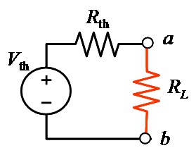
- The figure below shows a resistive load RL =
5 Ω connected to a Thévenin circuit with Vth =
20 V. For what value of Thévenin resistance is the power maximized?
Find the maximum power delivered to the load. (Hint: Be
careful, this is a trick question if you don't stop to think about
it.)
- Find the voltage vc in the circuit below
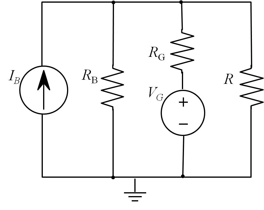
- (Rizzoni 3.41) Determine, using superposition, the voltage across R in the circuit below.
| IB | VG
| RB | RG | R |
|---|
| 12 A | 12 V | 1 Ω | 0.3 Ω | 0.23 Ω
|
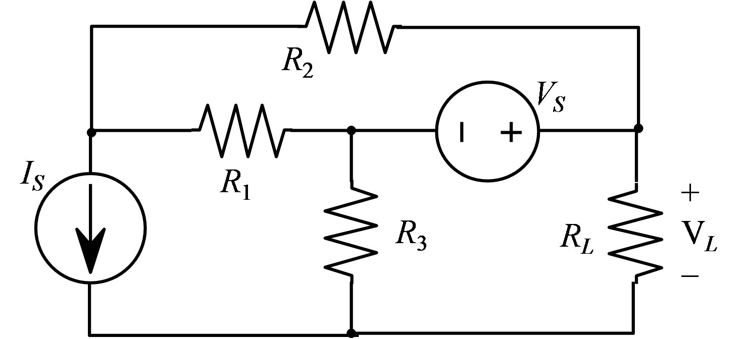
- Determine the Thévenin voltage and resistance of the circuit
below, given that R1 = 2 Ω,
R2 = RL = 4 Ω, Vs = 4 V,
and Is = 0.5 A.
Use the Thévenin
equivalent circuit to determine the power deliered to the load resistor.
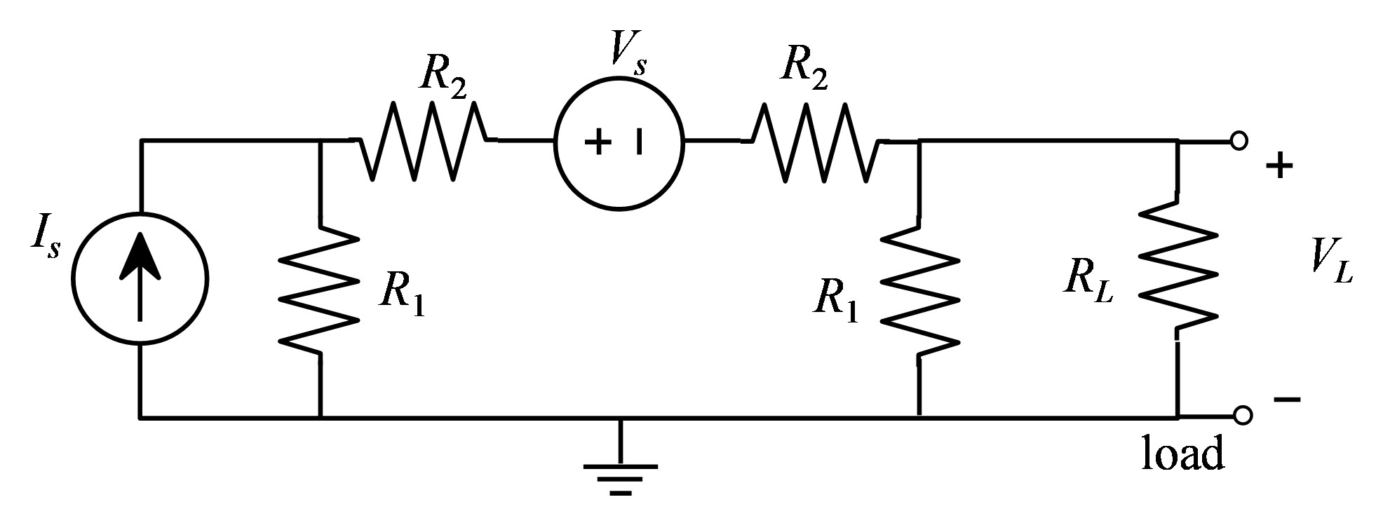
- Determine the Thévenin voltage and resistance of the circuit
below. Use the Thévenin
equivalent circuit to determine the voltage across and
current flowing through the load resistor.
| IS | VS | R1 | R2
| R3 | RL
|
| 2 A | 3 V | 2 Ω | 2 Ω | 4 Ω | 3 Ω
|
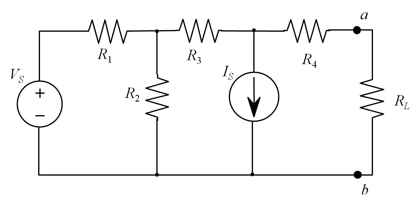
- (Rizzoni 3.55) Find the Thevenin equivalent resistance seen by the load resistor RL in the circuit below.
| VS | IS
| R1 | R2 | R3 | R4 |
|---|
| 10 V | 10 mA | 1 kΩ | 1 kΩ | 1 Ω | 3 Ω
|
Maintained by John
Loomis, last updated 17 September 2014