"The task" is that part of the optical system description that specifies how the lens must operate, including its spectral range, aperture size, and field coverage. Such parameters are specified as requirements and are generally not changed by CODE V except by specific user request. Whenever you start to define a new lens, you must specify these task parameters before CODE V can perform any meaningful analysis of the lens.
The most fundamental specifications of any lens are its spectral range (wavelengths) and its system aperture (f/number, entrance pupil diameter, or numerical aperture). These must always be provided by the user - there are no defaults provided. Other specifications are optional, though some are virtually always supplied by the user. Specific commands for various specification data items are described in detail in Chapter 2A, "Entering/Changing Data - Specification Data." You may find the following background information useful in interpreting several of the more common specification data commands.
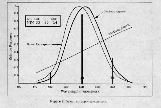
You may specify up to 21 discrete wavelengths at which the optical system will be analyzed and optimized, although 3 wavelengths will be sufficient for many tasks, and monochromatic systems naturally require only one. Because these discrete wavelengths are used in most options to simulate a continuous polychromatic distribution, spectral weights can be very important. The CODE V SPE option (Spectral Analysis - Chapter 9) is a very useful tool in determining suitable wavelengths and weights when the spectral responses of source, filter, and detector are known (or can be estimated). The following figure is based on data from the SPE option and shows source and detector spectral curves, the combined spectral curve, three discrete wavelengths chosen by the user (WL 640 560 480), and the spectral weights calculated by SPE to best fit the combined curve for these wavelengths (WTW 33 90 14).
You must also specify which wavelength the program is to use for such monochromatic calculations as first-order ray tracing (including derived quantities such as focal length), Seidel aberrations, and reference ray tracing. This is called the reference wavelength (the reference wavelength of 560 nm is highlighted in the above figure).
Pupil specification defines the size of the bundle of light used on-axis. Whether specified as f/number (FNO), entrance pupil diameter (EPD), or numerical aperture (NAO on object side, NA on image side), the pupil specification determines the unvignetted size of the light bundles from each field point. For complete definitions and recommendations, see Chapter 2A, "Entering/Changing Data - Specification Data - Pupil Specification." The pupil specification must be considered along with vignetting factors and surface apertures to understand the nature of light bundles that are used in various parts of CODE V. These relationships are discussed later in this introduction.
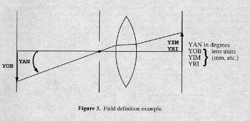
Although CODE V works only with individual point objects (not extended objects), you can define multiple field or object points as part of your lens data. Analysis options will provide output for each defined field; optimization is carried out simultaneously over all fields. Fields can be defined in four ways (the figure shows Y components only - X components are similarly defined). For usage recommendations, definitions, and command details, see Chapter 2A, "Entering/Changing Data - Specification Data - Field Specification."
The aperture stop surface is the surface whose aperture limits the axial bundle of light. By definition, chief rays from all fields go through the center of the aperture stop surface. The aperture stop can be placed on any surface, real or dummy, other than object or image. If you do not specify otherwise, CODE V assumes surface 1 to be the aperture stop. Aperture stop positioning varies depending on your application and can have major effects on aberrations and element sizes.
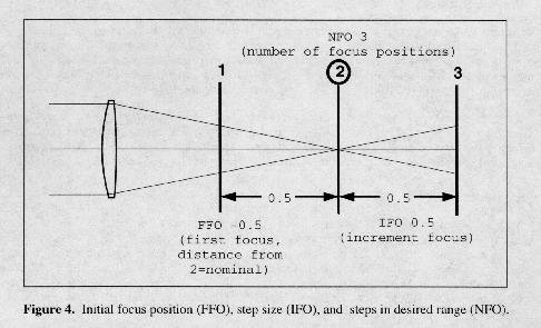
Some optical systems have performance specifications over a designated range of focus. As shown in the following example figure, CODE V provides commands for defining an initial focus position (FFO), step size (IFO), and up to 18 steps in the desired range (NFO).
When it is defined, through-focus data is used by most image evaluation options (CEF, GLS, LSF, MTF, PAR, PMA, PSF, QUA, RAD, SPO, and WAY). Note that the computation time and volume of output from these options can increase substantially when depth of focus is specified. Refer to Chapter 2A, "Entering/Changing Data - Specification Data - Depth of Focus" for details on these commands. AUT (automatic design) has separate commands for through focus optimization (see Chapter 3).
Vignetting factors are used when you want to specify a specific degree of vignetting. Vignetting factors must be considered along with system aperture and surface apertures to understand the nature of light bundles that are used in various parts of CODE V. These relationships are discussed later in this introduction.
Afocal systems have exiting beams that are nominally collimated (parallel), i.e., they do not form an image at a finite distance. CODE V handles such system through the mechanism of an "afocal perfect lens" that is defined by the user for the purpose of bringing the nominally collimated beams to a focus without introducing additional aberration. See Chapter 2A, "Entering/Changing Data - Specification Data - Afocal Systems" for details on the AFI and AFO commands that are used to define the afocal perfect lens.
The surface is the basic organizing unit in a CODE V lens description. A CODE V lens is made up of an object surface (where rays originate), an image surface (where rays terminate), and one or more user-defined surfaces, one of which is the aperture stop surface. Each surface represents a location of interest in the optical system, and various optically relevant data can be attached to this location, allowing it to represent (for example) an air/glass interface with a particular shape (curvature) and extent (aperture) in space. When rays are traced, they normally proceed from one surface to the next in sequential fashion, following the order in which the surfaces have been defined (non-sequential surfaces are a useful exception to this norm). CODE V allows you to define a large number of surfaces in a lens model (currently 250).
This chapter contains complete information on surface modeling. See in particular Chapter 2A, "Entering/Changing Data - Surface Shape and Position" for a detailed overview.
Dummy surfaces are those with the same material on both sides (air/air or glass/glass). Such a surface has no refractive effect and can thus be placed anywhere in an optical system setup. Dummy surfaces can represent mechanical stops, apertures, obscurations, mounts, baffles, etc.- in such cases, user-defined apertures are placed on dummy surfaces to enable them to block rays in image evaluation options. Dummies with default apertures will NOT block rays in image evaluation options.
It is always possible to ray trace to a dummy surface and determine ray coordinates there, regardless of its location - virtual ray tracing (essentially geometric extension of ray segments) is used when necessary to accomplish this (virtual ray tracing is not allowed in non-sequential surface ranges). Note, however, that such virtual ray segments extending to dummy surfaces are not generally shown on lens drawings.
Although we often talk about optical elements, CODE V does not explicitly define elements or other groups of surfaces in its lens database. Options that make use of elements and groups of surfaces may break surface data down into elements for reporting purposes. Elements and groups are most important in tolerancing, where the mounting structure of the lens must be approximated, and the LDM provides commands to define element and group tolerances in addition to surface tolerances (see Chapter 2A, "Entering/Changing Data - Tolerances" and also Chapter 6, "Tolerancing," for detailed information).
Surfaces can be inserted, deleted, and copied (both within the current lens and from other lenses stored in files). In all such operations, the affected surfaces are automatically renumbered and all associated data is updated to reflect this. The data associated with a surface (curvature, apertures, aspheric data, solves, etc.) can be queried, modified, or deleted (in most cases). Many operations can be performed on a specified range of surfaces, such as flipping a group of surfaces front to back, displaying the focal length of a specified group, or scaling a group of surfaces in various ways. These operations are discussed in Chapters 2B, 2C, and 2D.
Glass and air are the two most common optical materials, although other materials are often used as well (water, plastics, crystals, etc). The associated material for each surface is the one following the surface. Although index of refraction is the most important material property for optical systems, some options of CODE V can make use of other data as well (transmission, specific gravity, price, etc). The LDM allows you to define optical materials in several ways, described early in Chapter 2A (see "Entering/Changing Data -Materials"). Gradient index (GRIN) materials are described in the second half of Chapter 2A, "Entering/ Changing Data - Special Topics."
Surface shape refers to the refracting profile of the surface (flat, spherical, cylinder, aspheric, etc.). There are various ways to specify curvature, including solves. Position refers to the location and orientation of a surface with respect to other surfaces. This includes thickness/separation as well as thickness solves and various forms of tilts and decenters (including both local and global coordinate systems). These issues are all described in Chapter 2A, "Entering/Changing Data - Surface Shape and Position."
In addition to the basic parameters of surface shape, CODE V supports a wide range of special surface types. These extend beyond common aspheric surfaces to include holographic elements and even interferometric data. These are described in the second half of Chapter 2A, "Entering/Changing Data -Special Topics."
Some optical systems cannot be represented by a set of surfaces that are ray traced in invariant, sequential order. Corner cubes and certain other prisms are one class of such systems, while segmented windows and optical fibers are others. Many such systems can be modeled with CODE V's non-sequential surface (NSS) feature. Some of the rules for setting up and ray tracing must be modified for NSS systems. A complete section on this special subject is included in the second half of Chapter 2A, "Entering/Changing Data - Special Topics - Non-sequential Surfaces."
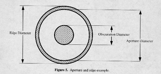
Apertures define the used or optically relevant portions of a surface. Although the general term "aperture" can be used to refer to apertures of all types, it usually refers to the outer extent of this portion (the term "clear aperture" is also used). Obscurations (optional) define the inner extent of the used portion. Edges refer to the physical extent of the surface rather than its optical extent. As shown in the figure below, rays are blocked if they fall outside of the aperture or inside the obscuration (shaded areas). Surfaces can have multiple apertures, edges, and obscurations when necessary. Circular, elliptical, and rectangular shapes are supported. Additional comments relating to apertures are included later in this introduction (see "Reference Rays, Vignetting, and Apertures"). For complete details, see Chapter 2A, "Entering/Changing Data - Element Structure - Apertures."
Non-sequential surfaces (NSS) are used to model optical systems with unusual geometries or other special properties. In NSS systems, edges are much more important than for normal systems, and a special aperture type (hole) is defined which applies only to NSS systems. Please see the second half of Chapter 2A, "Entering/Changing Data - Special Topics."
Some types of information are applicable only in a subset of options. First surface mirror substrate information (backing material and shape) does not affect raytracing but can be important for lens drawing, thermal modeling (ENV option), and for weight and cost calculations. Cements (between cemented components) and coatings (single layer or multilayer) can be important in calculating transmission and whenever polarization is considered in diffraction based options. These specialized lens data items are described in Chapter 2A, "Entering/Changing Data - Element Structure."
When optical elements are fabricated, their design parameters must be held within certain limits if the lens system is to perform as intended. These limits are called tolerances, and they are defined for most of the parameters that define a lens in CODE V (thickness, decentration, index of refraction, etc). Although tolerances are calculated and used primarily within the tolerancing options (see Chapter 6), they are considered to be part of the lens database and can be defined, viewed and modified within the LDM. These capabilities are covered in Chapter 2A, "Entering/Changing Data - Tolerances."
Certain special purpose data is considered to be part of lens data by CODE V. Additional information must be added to the lens database to simulate zoom or ml: ticonfiguration lenses (scanners, attachments, etc). Special considerations and commands apply to such systems. Before optimization can be done (AUT option, Chapter 3), free variables and any coupled groups of variables must be defined. This task is done in the LDM and the control codes are stored as part of the lens database. Zoom features are discussed in Chapter 2A, "Entering/Changing Data - Zoom (Multi-configuration) Systems." Variables and control codes are discussed in Chapter 2A, "Entering/Changing Data - Variables and Control Codes." The Delete section contains a combined list of commands to delete various attributes of the lens database (gathered for reference from various sections of Chapter 2).
Excerpted from the CODE V Reference Manual. (c) Copyright 2002 by Optical Research Associates. Excerpted by permission of Optical Research Associates. All rights reserved. No part of this excerpt may be reproduced or reprinted without permission in writing from Optical Research Associates.
Maintained by John Loomis, last updated 24 June 1999