CODE V uses right-handed coordinates. In a centered optical system, the nominal optical axis is the z-axis. As you look from object space toward image space (+z direction)
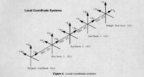
Each surface in a CODE V lens has its own local, right-handed coordinate system. In a centered, sequential system, these local coordinate systems are related by a simple translation along the Z axis (THI, or thickness to next surface - see figure).
In a decentered system, coordinate breaks are used to model tilts and/or decanters. See Chapter 2A "Entering/Changing Data - Tilts and Decenters" for a detailed discussion of the many issues involved in describing non-centered systems.
When data for one surface is defined or viewed in the coordinate system of another surface (rather than in the surface's own local coordinate system), we refer to these as global coordinates. Global coordinates are particularly useful when setting up, analyzing, and optimizing tilted and decentered systems, and they are discussed in this context in Chapter 2A under "Entering/Changing Data - Tilts and Decenters." One of the requirements for setting up non-sequential surfaces is that they be positioned with global coordinates. NSS systems are explained in the second half of Chapter 2A, "Entering/Changing Data - Special Topics - Non-Sequential Surfaces."
When you look at output from CODE V, you need to understand the coordinate system in which the data is expressed and how this relates to the lens model you are using. Some output represents data on the image surface (spot diagram, PSF). The FOO (footprint) option displays ray distributions on any specified surface. Other options represent wavefront or other data in the exit pupil (PMA). Most of these options display the data as seen from the image surface, looking in the -z direction. The figure below demonstrates this for a footprint on the image surface (essentially a spot diagram showing both fields that are defined for this lens).
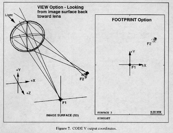
The two exceptions to this interpretation of CODE V output are the CAT (catseye diagram) and FOV (field of view) options. These portray the data from object space, looking in the +z direction (see Chapter 4).
CODE V can import interferometric data (interferograms) from various sources, attach the data to specified surfaces, and calculate the effect of these perturbations on ray trace and wavefront data. Although the interferogram interface is quite easy to use, coordinate systems are often a problem. This is because the conventions of interferometry differ somewhat from those of lens design. Coordinates and sign conventions are explained completely in the second half of Chapter 2A, "Entering/Changing Data - Special Topics -Interferometric Deformations and Intensity Apodization."
Excerpted from the CODE V Reference Manual. (c) Copyright 2002 by Optical Research Associates. Excerpted by permission of Optical Research Associates. All rights reserved. No part of this excerpt may be reproduced or reprinted without permission in writing from Optical Research Associates.
Maintained by John Loomis, last updated 24 June 1999