Thickness is the distance along the Z axis from the current surface vertex to the next surface vertex. If the next surface lies to the RIGHT of the current surface (+Z), thickness is POSITIVE. If the next surface lies to the LEFT of the current surface (-Z), thickness is NEGATIVE. Note that when modeling reflecting systems, the you must alternate the signs of thicknesses after each reflection:
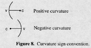
Curvature (CUX, CUY) is the reciprocal of radius of curvature (RDX, RDY), and the same sign conventions apply for both (note that curvature is the primary definition of surface shape for CODE V). A curvature of zero indicates a plane surface (for convenience, a zero value entered for radius of curvature is also interpreted as piano). The sign convention for curvature is as follows:
This is demonstrated in the following diagram, where c represents the center of curvature and v indicates the surface vertex.
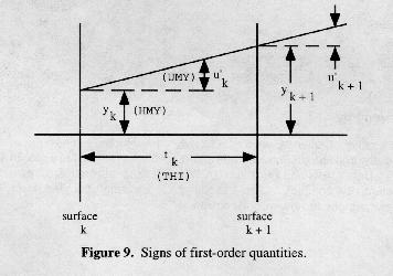
The first-order or paraxial ray trace quantities are ray heights (measured on the surface tangent plane), ray slopes (tangent of the ray angle), and paraxial angle of incidence. These quantities are used to calculate effective focal length (EFL) and other paraxial constants. Data is calculated for two paraxial rays, the marginal ray (sometimes called axial ray - passes from center of object through edge of paraxial entrance pupil) and the chief ray (sometimes called the principal ray - passes from edge of object surface through center of paraxial entrance pupil). In the figure below, y and u' are POSITIVE. Commands used to display first-order properties are discussed in Chapter 2D, "Quick Analyses."
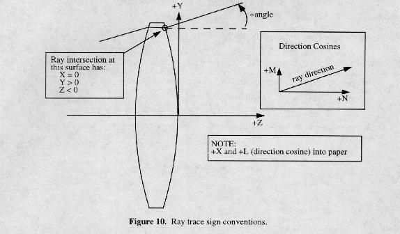
Ray trace sign conventions are important in interpreting the output from single ray tracing (RSI, SIN) and in using reference ray data, either in Macro-PLUS expressions or as constraints in optimization. By default, ray information is expressed in the local coordinates of each surface, following the definitions discussed above ("Local Coordinate Systems"). Ray data can also be displayed and used in global coordinates, relative to the coordinate system of any specified surface. The following figure illustrates the sign conventions for ray coordinates, ray angles, and direction cosines.
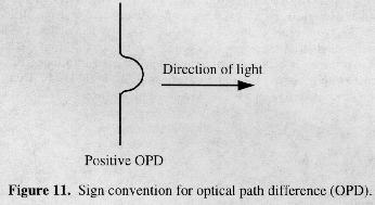
The sign convention for optical path difference (OPD) is that a leading wavefront produces a positive OPD. The small deviation in the wavefront below illustrates a positive OPD.
There are a number of other parameters in CODE V for which sign conventions apply. Vignetting is discussed later in this introduction. Signs for tilts and decenters are defined in a special section (Chapter 2A, "Entering/Changing Data - Tilts and Decenters"). When dealing with interferometric data, signs are very important and potentially complex. See Chapter 2A, "Entering/Changing Data - Special Topics -Interferometric Deformations and Intensity Apodization."
Excerpted from the CODE V Reference Manual. (c) Copyright 2002 by Optical Research Associates. Excerpted by permission of Optical Research Associates. All rights reserved. No part of this excerpt may be reproduced or reprinted without permission in writing from Optical Research Associates.
Maintained by John Loomis, last updated 24 June 1999